This is done to pull the output of the hall effect sensor to 5v.
Hall effect wheel speed sensor arduino.
The signal from the sensor is shown and can be downloaded.
If you remember the arduino waterflow sensor tutorial we implemented earlier the main component of the water flow sensor is the hall effect ic.
A hall effect sensor works on the principle of well hall effect.
Various hall effect sensors.
The gnd of the sensor is connected to the gnd pin on the arduino.
The hall effect sensor is a very useful sensor to use in many projects.
Achim and shutterdrone s suggestion to use a reed switch makes more sense though given the supporting hardware a hall effect sensor requires to get a clean digital signal.
How fast can a fidget spinner spin.
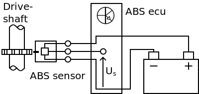
With a lab scope a 2 wire hall effect abs sensor signal voltage is measured with the wheel turned by hand.
A simple guide to using a hall sensor measuring rpm arduino link sketch.
How to make fidget spinner rpm counter g.
It is very easy to use as you can see in this easy arduino tutorial.
Simply speaking a hall effect sensor or ic detects motion position or change in magnetic field strength of either a permanent magnet an electromagnet or any.
Arduino uno tutorial 11 hall effect switch.
Using a hall effect sensor as starliner suggested will be one way to interface with the wheel.
Rpm measurement using hall sensor and arduino.
How to control the speed of a dc motor with the arduino.
The hall effect sensor.
Useful links and tutorials on hall effect sensor.
In the following steps i ll describe the parts ne.
Furthermore a 10k resistor is connected between the vcc and vout pins of the hall effect sensor.
The vout or signal pin of the hall effect sensor is connected to the arduino s interrupt pin digital pin 2.
To help determining whether the 2 wire hall effect abs sensor is functioning correctly different deviations from the example signal are mentioned along with possible causes.

